 Gil’s Garage
Gil Baumgartner
CTCI Authenticity Chairman
No doubt the ignition coil is one part that has been changed when it still has many years of service remaining. It is very simple to verify the condition of the primary and secondary circuits of the coil by measuring the ohms resistance. This can be accomplished with a fairly inexpensive multimeter available from most auto parts stores. Most automotive type multimeters come with a how-to instruction manual for testing various components including checking the coil.
The basic meter will have a black and a red lead, plug the black lead in the receptacle lead marked common (grd), plug the red lead into the receptacle lead marked ohms.
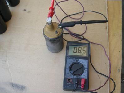
Check the primary circuit of the coil by rotating the multimeter switch to the 200 range, connecting the red lead to the BATT (+) terminal post and the black lead to the DIST (-) terminal post on the coil. The typical resistance range for the primary circuit should be 0.3 – 2.0.
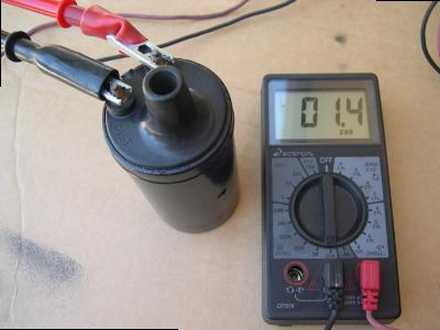
Check the secondary circuit of the coil by rotating the multimeter switch to 200K, leave the black lead connected to the DIST (-) terminal post on the coil, and connect the red lead to the secondary terminal of the coil (where the coil wire plugs in). The typical resistance range for the secondary circuit should be 6.0 – 30.0 K.
The coil should also be checked when it is hot to insure the circuit is not breaking down when it reaches operating temperature.
Gil Baumgartner