 Gil’s Garage
Gil Baumgartner
CTCI Authenticity Chairman
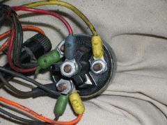
 The wiring diagram can be confusing, especially the ignition switch, for anyone using the FoMoCo Electrical Equipment Installation Manual for the first time. The manual has been reproduced and is available from CTCI, item number110-25. The wiring is correct but the drawing of the back side of the ignition switch for the 1955 on page 18 and the 1956 on page 57 is not correct. It shows the post for the start wire (red/blue) #32 on the outer circumference of the switch with the other three post instead in the center as it was original made. The 1957 portion of the manual on page 99 corrected the drawing except for View F.
All three years use the same switch and the wires are connected the same. The wire numbers are found in the manual and references the color codes that are found on the wiring harness.The back of the switch is marked as follows:
BATT- #21 yellow wire, supplies voltage to the switch.
ACC – #30 black with green – fuel and temp gauge, #8 orange with yellow – turn signal, also attached is other accessories radio heater, etc. Note: Some accessory wires do no have rubber molded ends. The wire goes straight to the eyelet.
IGN – #16 red wire with green attaches to the coil on a 1955 and to the ignition resistor on a 1956/57, #30A,30B black with green wire attaches to oil pressure and generator light. The eyelet is single with the wires clustered together.
ST- #32 (the center post) Red/blue wire is energized when the ignition switch is held in the start position. It supplies voltage to the starter solenoid which engages the starter.
A single sheet electrical wiring schematic (non FoMoCo) is also available from CTCI item #110-41. The back side ignition switch is not marked to coincide with the markings on the switch but it is functional and fairly easy to decipher. The diagram is marked as follows:
B – BATT
A – ACC
C – IGN
S – ST
Also (brought to my attention by C.L. Hood) be advised that on some of the non FoMoCo Schematics the B-G wire is on the Batt post of the switch which would cause the fuel and temp gage to read at all times. This has been corrected with white out on most of the schematics.
Gil
