 Gil’s Garage
Gil Baumgartner
CTCI Authenticity Chairman
When installing a reproduced heater control plastic faceplate (P/N 18619) the letters do not illuminate when the dash lights are turned on.
Investigation reveals that the reproduction faceplates are totally blacked out on the backside and will not allow the letters to illuminate.
Until this problem is fixed by the parts vendors it can be corrected by sanding or scraping the black coating from the back side outer edges which will allow light to reflect and illuminate the letters.

(click on picture for larger image)
(click on picture for larger image)
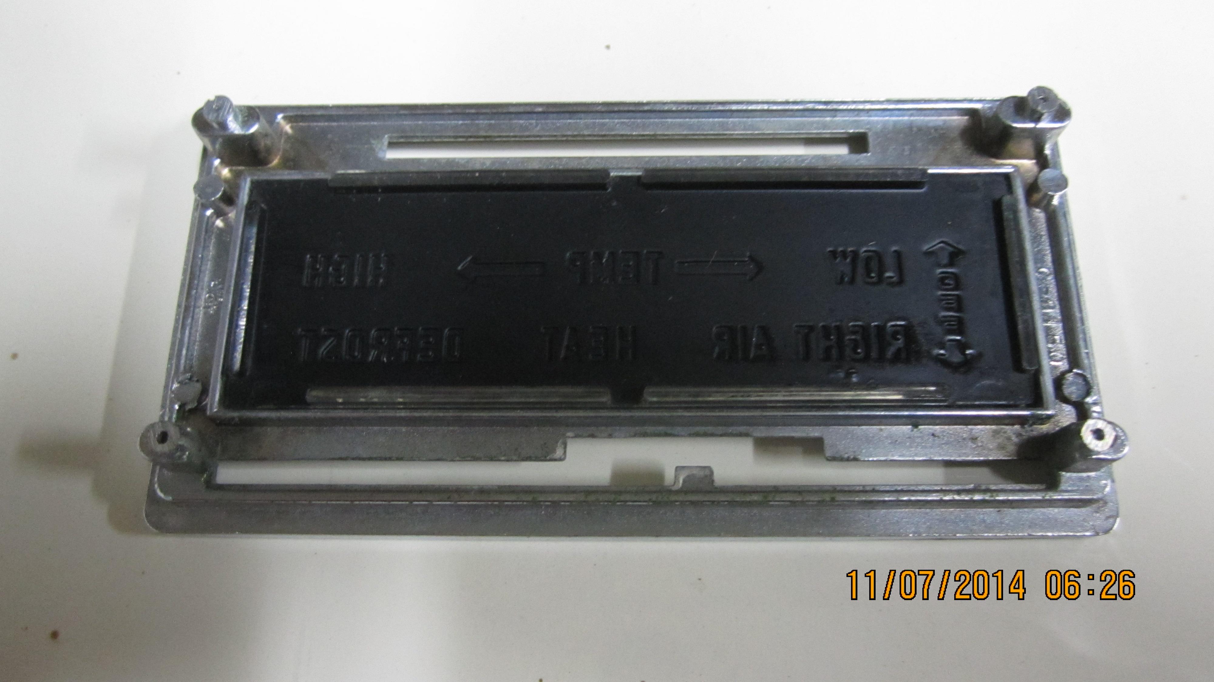
Image 1806 above shows a reproduction faceplate in the upper portion of the photo that is totally blacked out. The faceplate in the bottom portion of the photo is an original.
The six raised outer edges of the original plate are clear allowing light reflection to the letters on the faceplate when the headlamps are on.
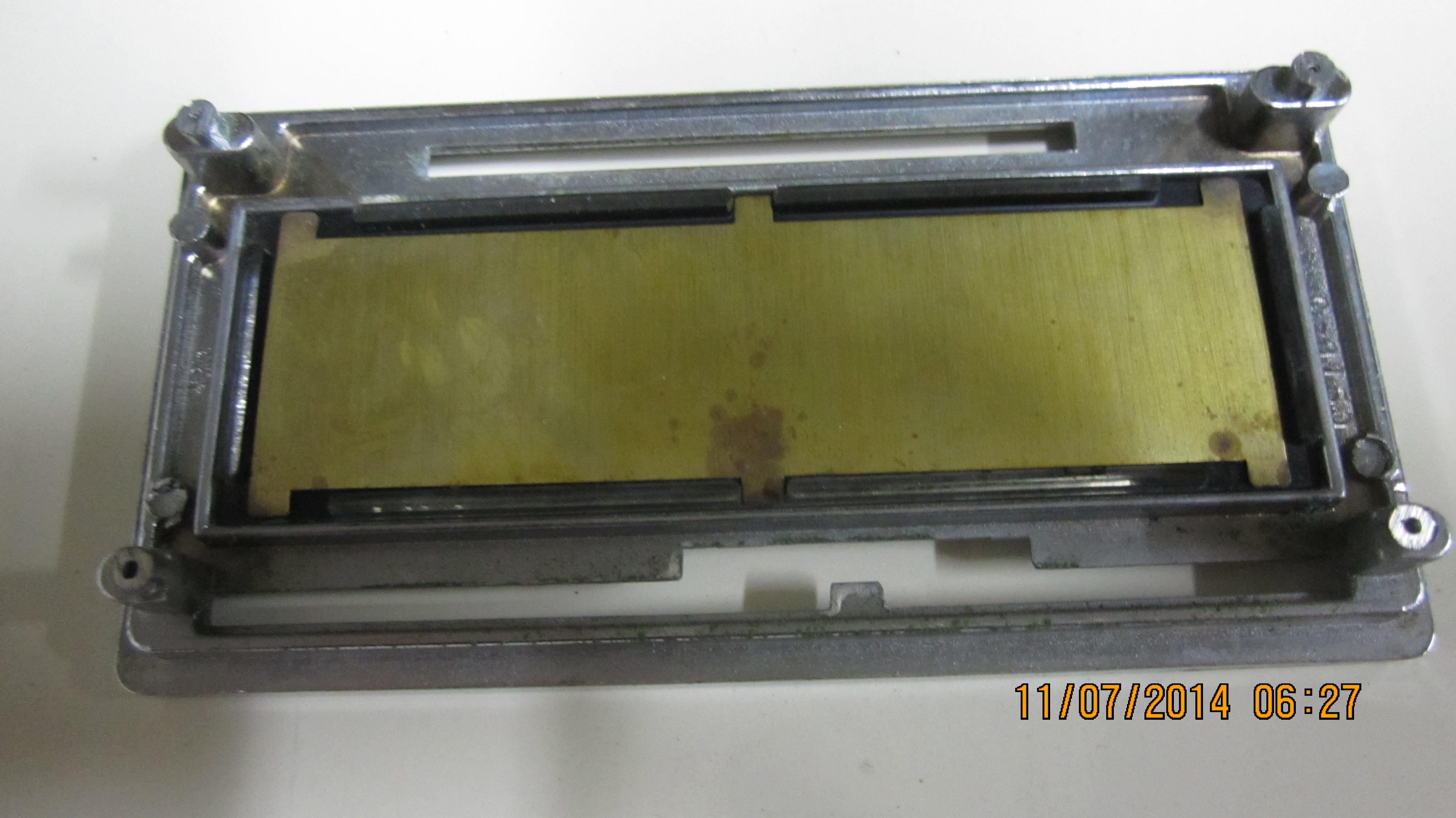
Image 1808 shows an original face plate inserted into the chrome housing the cleared edges are there, but not clearly visible in this photo.
(click on picture for larger image)
(click on picture for larger image)
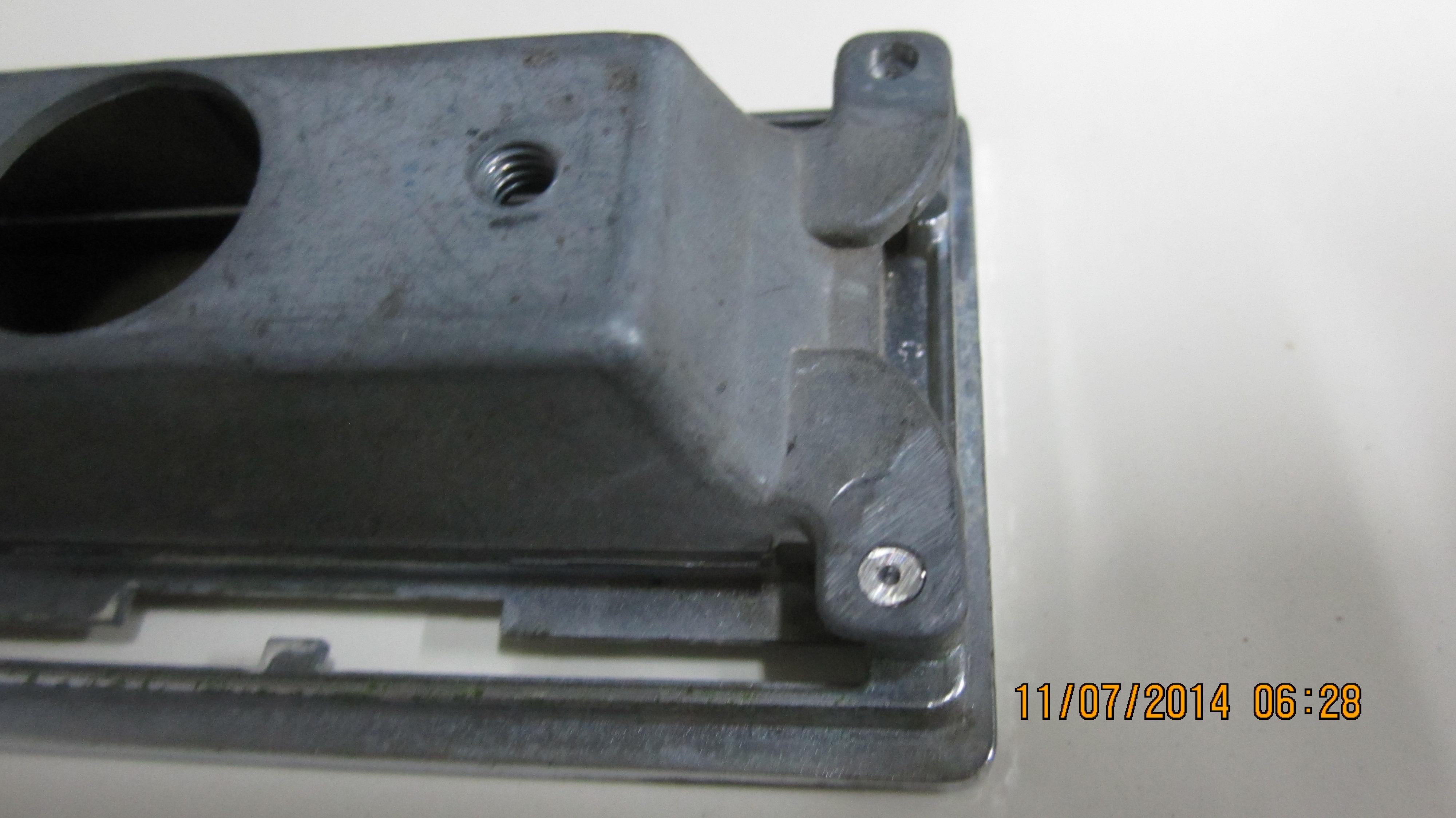
Image 1809 shows the heater face backing plate (P/N 18620) covering the back side of the plastic faceplate except for the raised edges.
The purpose of the backing plate is to help reflect light inside the bulb housing to the edges of the plastic faceplate. It also protects the plastic faceplate from being distorted by the heat of the light bulb.
Image 1811 shows the bulb housing being installed onto P/N 18550 over the plastic faceplate and metal backing plate (P/N 18620). Once the housing is aligned and pressed onto the four alignment pins the pins they are then peened over, securing the bulb housing to the chrome faceplate housing.
(click on picture for larger image)
(click on picture for larger image)
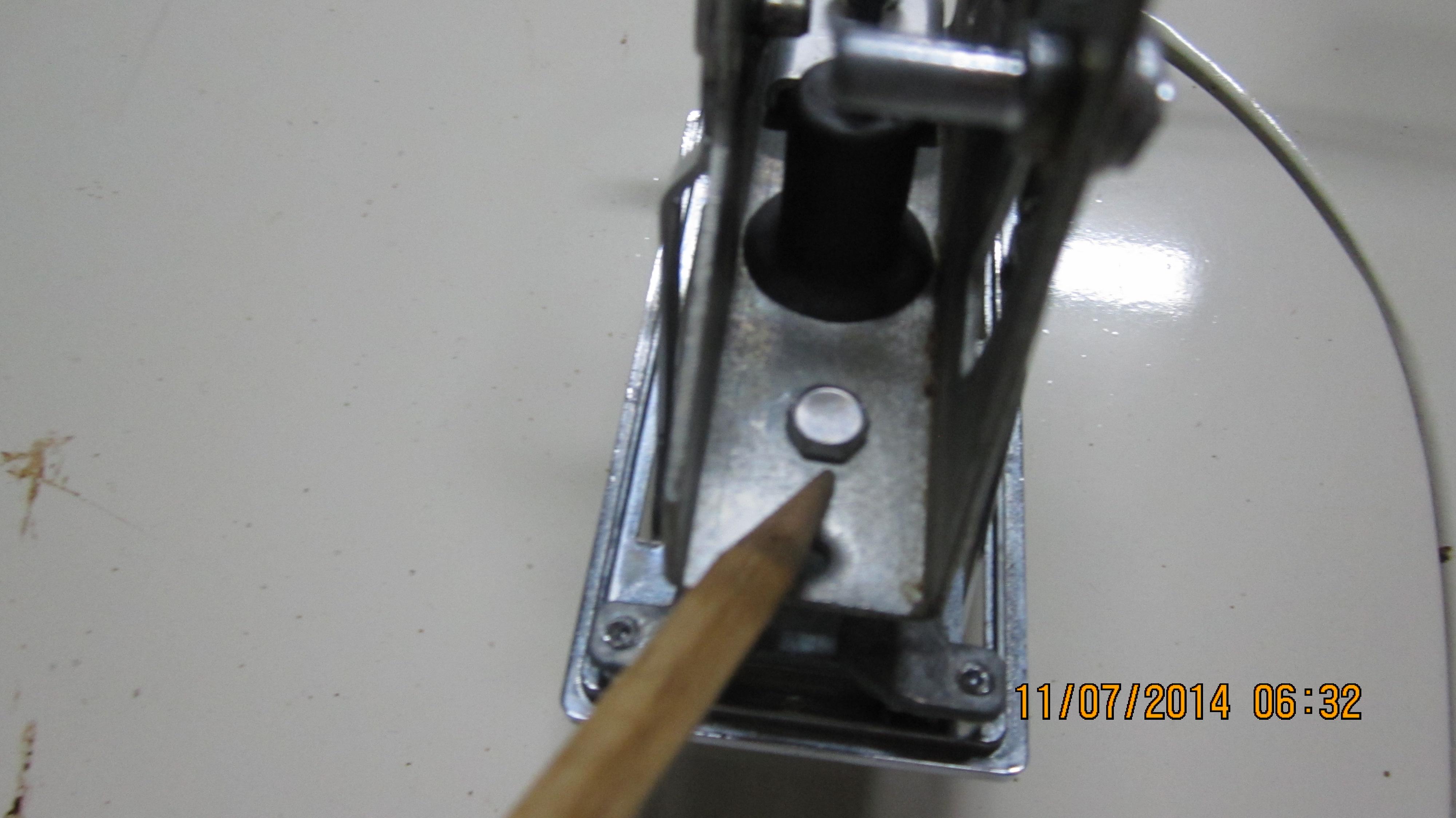
Image 1812 shows the lever mechanism attached to the face plate housing assembly with two bolts, one on each side of the bulb. One of the bolts is shown in this photo.
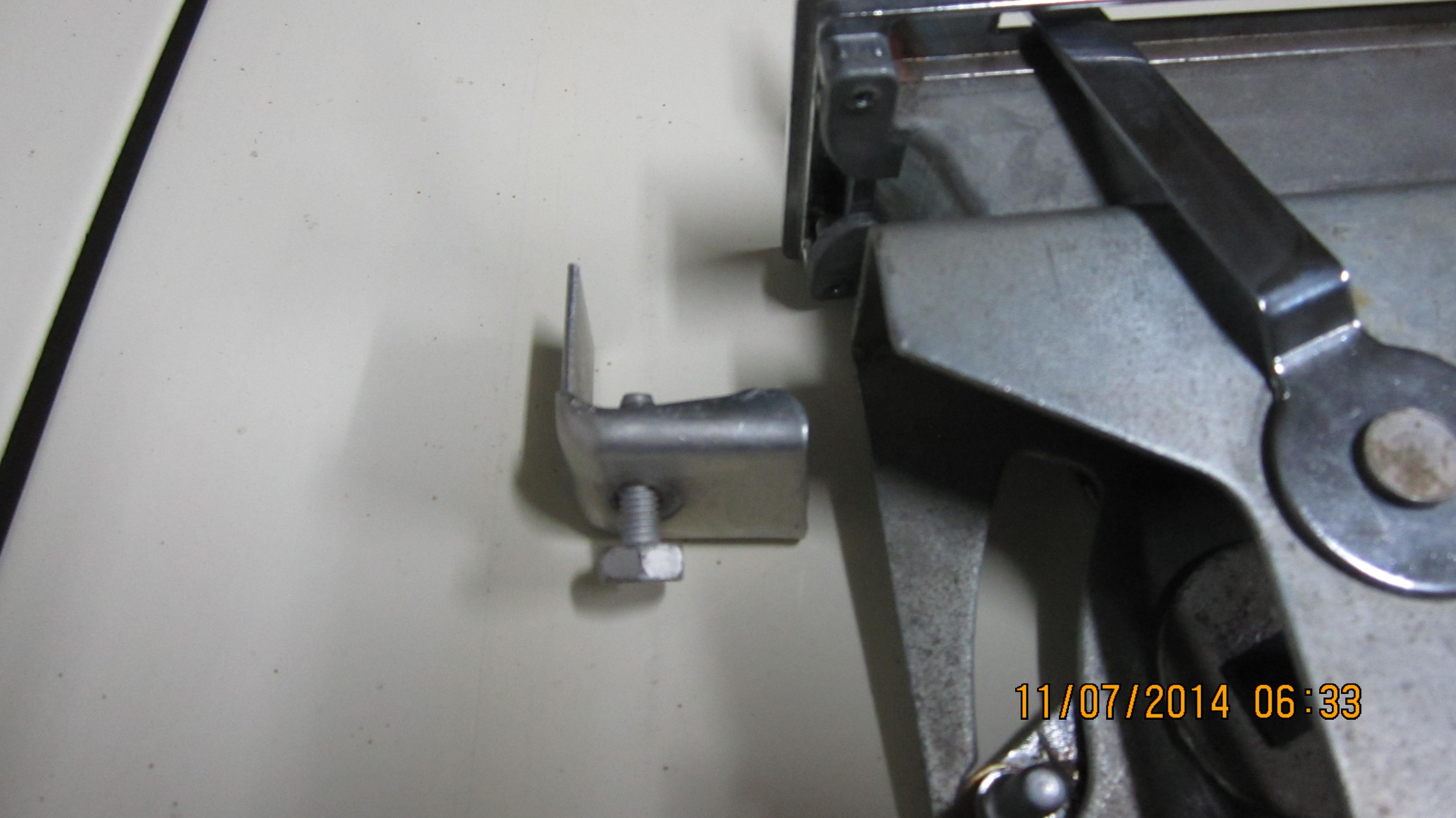
Image 1813 shows one of the two clamp brackets that secure the complete assembly to the dash.
Use caution when tightening these bolts, over tightening can result in separating the faceplate housing (P/N 18550) from the bulb housing.
Gil Baumgartner