 Gil’s Garage
Gil Baumgartner
CTCI Authenticity Chairman
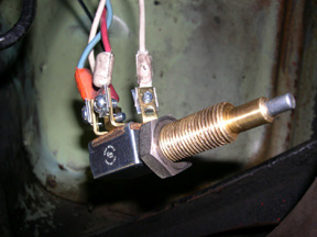 If you have attempted to install or replace an overdrive kick down switch without the benefit of the original switch with proper color coded wires intact it can be a little testy . The wiring diagram in the Electrical Manual is good but it fails to show which is the top or bottom of the switch. The wiring color codes for all three years are identical. The two connectors at the top of the switch near the floor have continuity and provide a circuit from the overdrive relay in the engine compartment through a red wire with a white tracer or white end to the kick down switch. The opposite top terminal connects a white wire to the overdrive governors yellow wire.
The governor is a centrifugal switch which completes a circuit at approximately 22 MPH providing a ground to the relay on the firewall which provides voltage from the relay through a blue wire to the overdrive solenoid which engages the overdrive. The overdrive will stay engaged as long as the vehicle speed is over approximately 22 MPH or disengaged through the kick down switch. The lower two connectors on the kick down switch have an open circuit the white wire with red tracer or red end connects to the distributor The other wire blue with orange tracer or orange end connects to the orange wire of the overdrive solenoid.
The overdrive kick down switch is mounted under the gas pedal. At cruise or above 22 MPH if the gas pedal is pushed to the floor the kick down switch completes the circuit on the lower two terminals which momentarily grounds the coil and overdrive solenoid causing the overdrive to disengage. It will re-engage automatically when the gas pedal is released from the kick down switch unless the overdrive manual cable was pulled out during acceleration.
Gil