 Gil’s Garage
Gil Baumgartner
CTCI Authenticity Chairman
Converting to disc brakes on your Thunderbird will provide you with significantly improved braking, and is not a hard conversion to make. The photos included, and description provided, are related to the disc conversion kit available from Thunderbirds One in Gastonia, NC.
On all of the installations I have performed, I have removed the hydraulic brake light switch and installed a mechanical switch from CASCO. On the conversion shown here, the brass block for the brake light switch has been completely removed to clean up the installation, and reduce the number of joints. All conversions have included switching to DOT5 silicone brake fluid.
A dual master cylinder is installed to separate the front brakes from the rear. The original push rod should be replaced with an adjustable push rod which can be adjusted to take up slack between the push rod end and the master cylinder piston. The new push rod is installed lower on the brake pedal so it will increase the master cylinder piston travel. The rod has a swivel (Heim) joint on the end that attaches to the brake pedal. The adjustable rod is available from several of the Thunderbird parts dealers.
Disc brake calipers are designed to operate at higher hydraulic line pressure than original drum brakes, as a result it is very beneficial to have a power brake booster. These steps are written presuming you have a power booster on your car. If not, the brake fluid lines would be slightly different. A booster is highly recommended. Even with a booster these brakes will not give you the feel of the disc brakes on your new vehicle, it still takes a bit of pedal pressure. The biggest advantage is the straight, true stopping, and the resistance to fade.
It is recommended to leave all hydraulic fittings loose until everything is in place and all clearances are checked.
New rear wheel cylinders are provided with the kit. The different diameter in them eliminates the need for a proportioning valve.
Please read these steps completely prior to beginning your work.
Click on thumbnail image for full size picture. The picture will open in a new tab or window (depending on your browser settings).
| 1. | Securely place the car on jack stands. | |
| 2. | Remove the front and rear wheels. | |
| 3. | Remove the master cylinder and the brake fluid line to the brass block. | |
| 4. | Remove the front brake drums, brakes, and backing plates. | |
| 5. | Remove the brake flex hoses from the frame to the wheel cylinders. | |
| 6. | Flush the front brake cross over line with an aerosol brake cleaner. | |
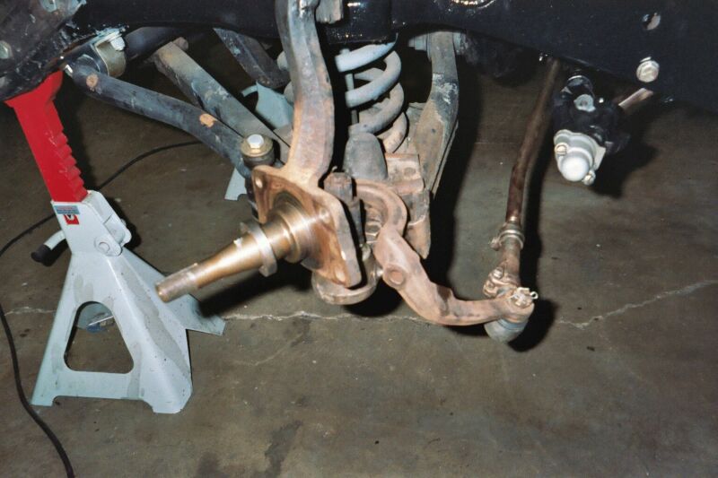
| 7. | Thoroughly clean the spindle and all related parts. | |
| 8. | Temporarily install the new backing plate provided using the original bolts. | 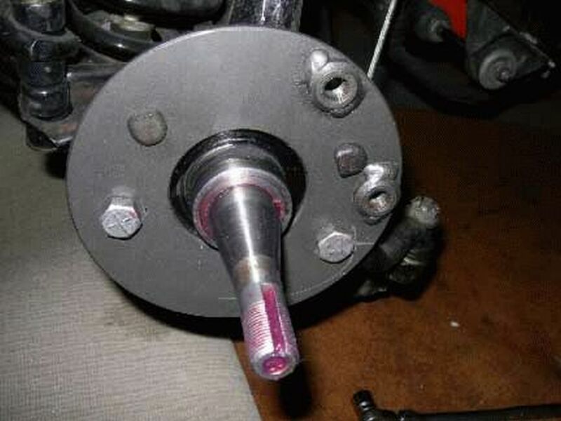 |
| 9. |
Dry fit the two caliper mounting bolts and spacers into the plate.
|
 |
| 10. |
Install the seal spacer on the spindle, beveled side in, shown in the picture.)
|
 |
| 11. | Properly grease the bearings and install in the rotor along with the grease seal. | |
| 12. | Install the rotor on the spindle; properly adjust the spindle nut. | 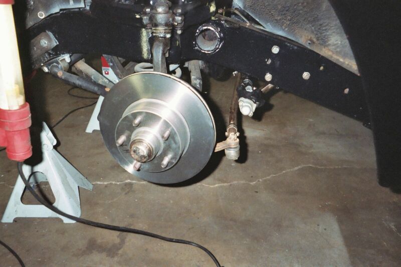 |
| 13. | Install the caliper on the backing plate. | 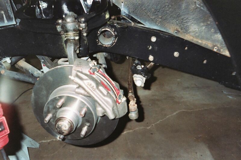 |
| 14. | Install the caliper brake fluid line cross over. | 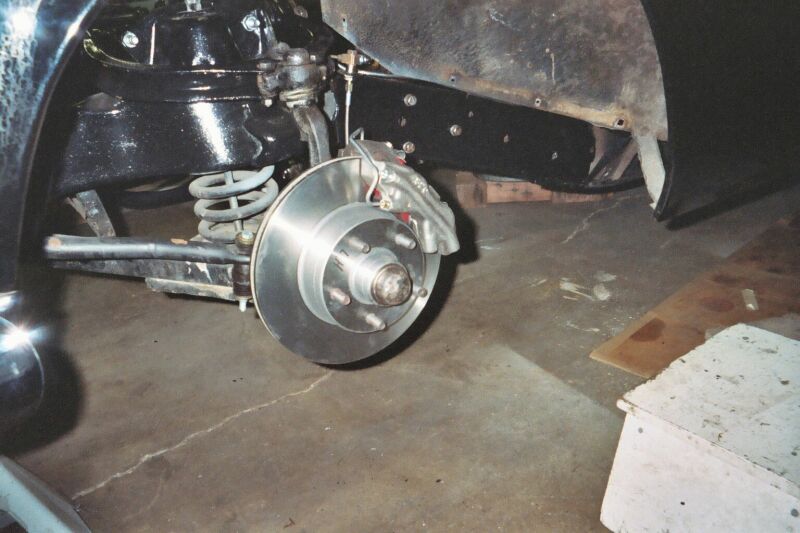 |
| 15. | Bench bleed the new master cylinder per standard procedures with DOT 5 fluid. | |
| 16. |
Install the new master cylinder using two of the original four mounting bolts.
|
|
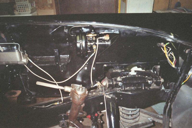
| 17. | Using the new flex steel lines install the longest of the lines from the rear of the master cylinder to the inlet (closest to the diaphragm) of the brake booster. | 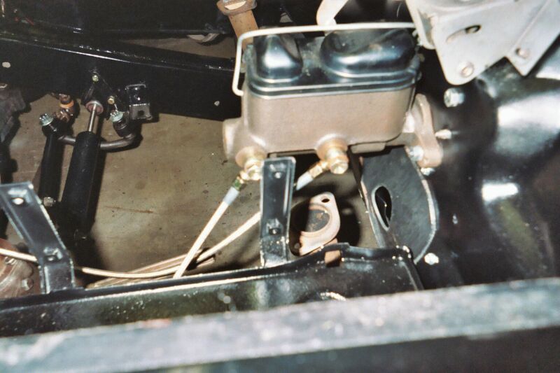 |
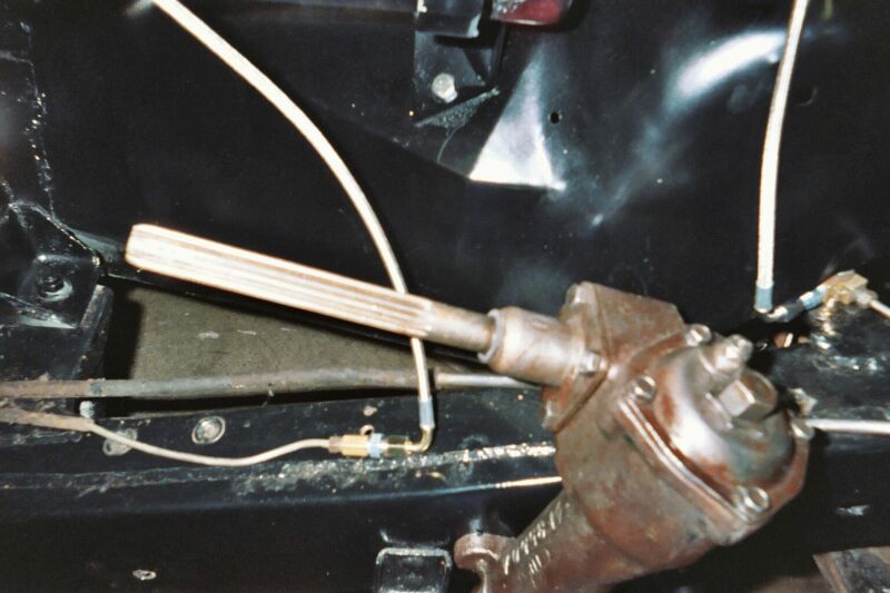
| 18. | Install a second flex steel line from the output of the booster to the junction block on the frame above the left front wheel. Closer view in lower picture. |
|
| 19. | Install the shortest flex lines from the frame blocks to the calipers. | 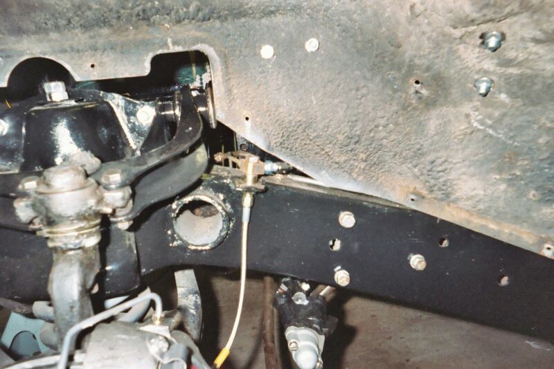 |
| 20. | Remove rear brake drums and wheel cylinders. | |
| 21. |
Flush the brake line from the brass block on the frame to the rear of the vehicle.
|
|
| 22. | Install the new rear wheel cylinders and attach the brake fluid line to them. | |
| 23. | Install new rear shoes and drums if needed (not part of kit). | |
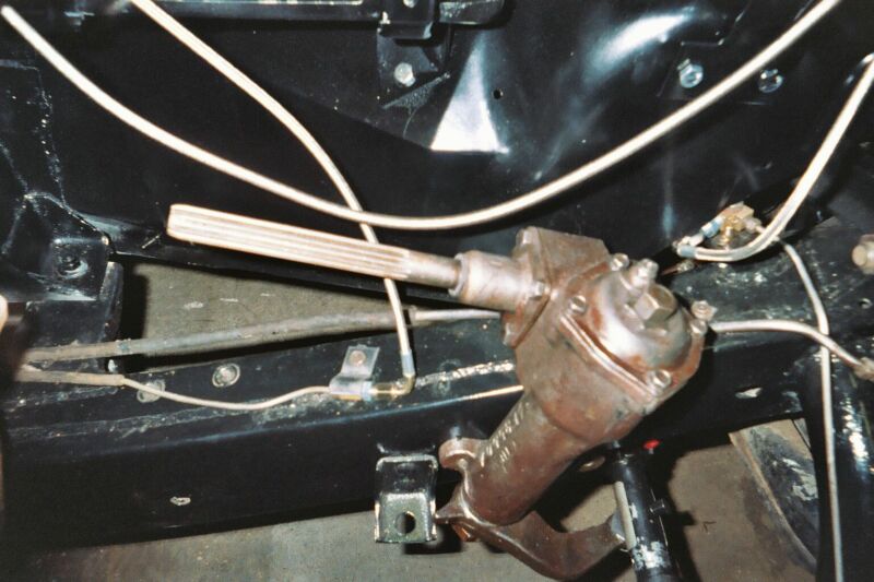
| 24. | Install last flex steel tubing from front of master cylinder to junction block on frame. |  |
| 25. |
Use brass plugs to plug holes in block where front tubing used to attach and where the brake light switch mounted.
|
|
| 26. | Most of the flex line installation is shown in picture. | 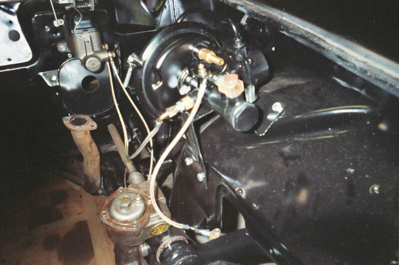 |
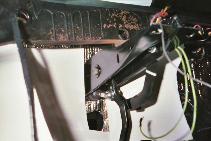
| 27. |
Follow the instructions provided with the new adjustable push rod (not part of disc brake kit).
|
|
| 28. | Following instructions provided install the mechanical brake light switch on the brake pedal (same pictures as step 27) (not part of disc kit). | |
| 29. | Verify that all hydraulic lines are free from moving parts that may rub them (A-Arms, etc). | |
| 30. | Tighten all hydraulic fittings. | |
| 31. | Bleed entire brake system. | |
| 32. | Install all four wheels. | |
| 33. | Verify mechanical brake light switch is working by having an assistant check brake lights. | |
| 34. | Lower car to ground and road test. |


Note. If the conversion is not made by a certified brake technician it is highly recommended that a brake inspection be performed by a certified brake inspection station.
Article and photos submitted by John Sailors