 Gil’s Garage
Gil Baumgartner
CTCI Authenticity Chairman
This article and accompanying photos will provide some basic information about the Dial-0-Matic seat installed in some late 1957 Thunderbirds.
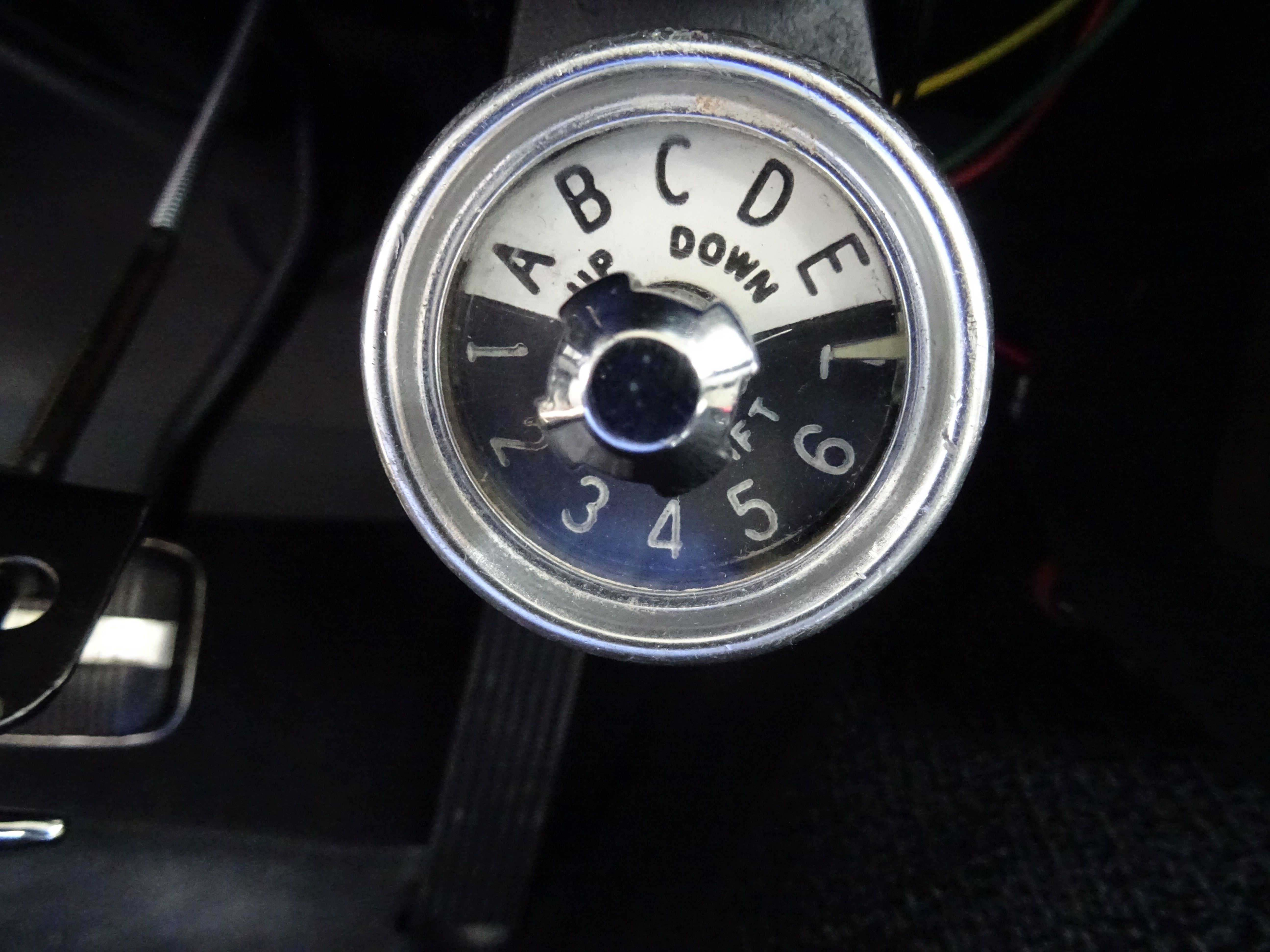

Photo # DM1 shows the controls mounted lower dash center. The outer ring controls the forward/aft (horizontal) movement on the seat which has seven different positions, the forward/aft (horizontal) motor and actuator is located under the seat. The center knob controls the up/down (vertical) movement and has five different positions, the up/down (vertical) motor and actuator is mounted behind the seat. The mechanical actuators are the same as a standard four way power seat. The motors are very similar to the standard four way power seat motors exception being they are modified to accommodate a wafer switch that controls each position as it is selected on the control head.
Photo # DM2. shows a relay, referred to as the entry relay, it is mounted in the engine compartment just above the data plate and controls the forward/aft seat motor only. When the ignition key is turned on voltage is supplied to the relay which moves the forward/aft motor to its last preset position. If the outer ring was preset to position 7 it will not move and will remain in the aft position until another position is selected. When the ignition key is turned off the seat moves to the most aft position unless it was previously preset to position 7 the most aft position. In position seven and the ignition key turned off the relay will have voltage on the red, blue and green wire. In the other six positions 1-6 with the ignition turned off voltage will be on the red and green wires.
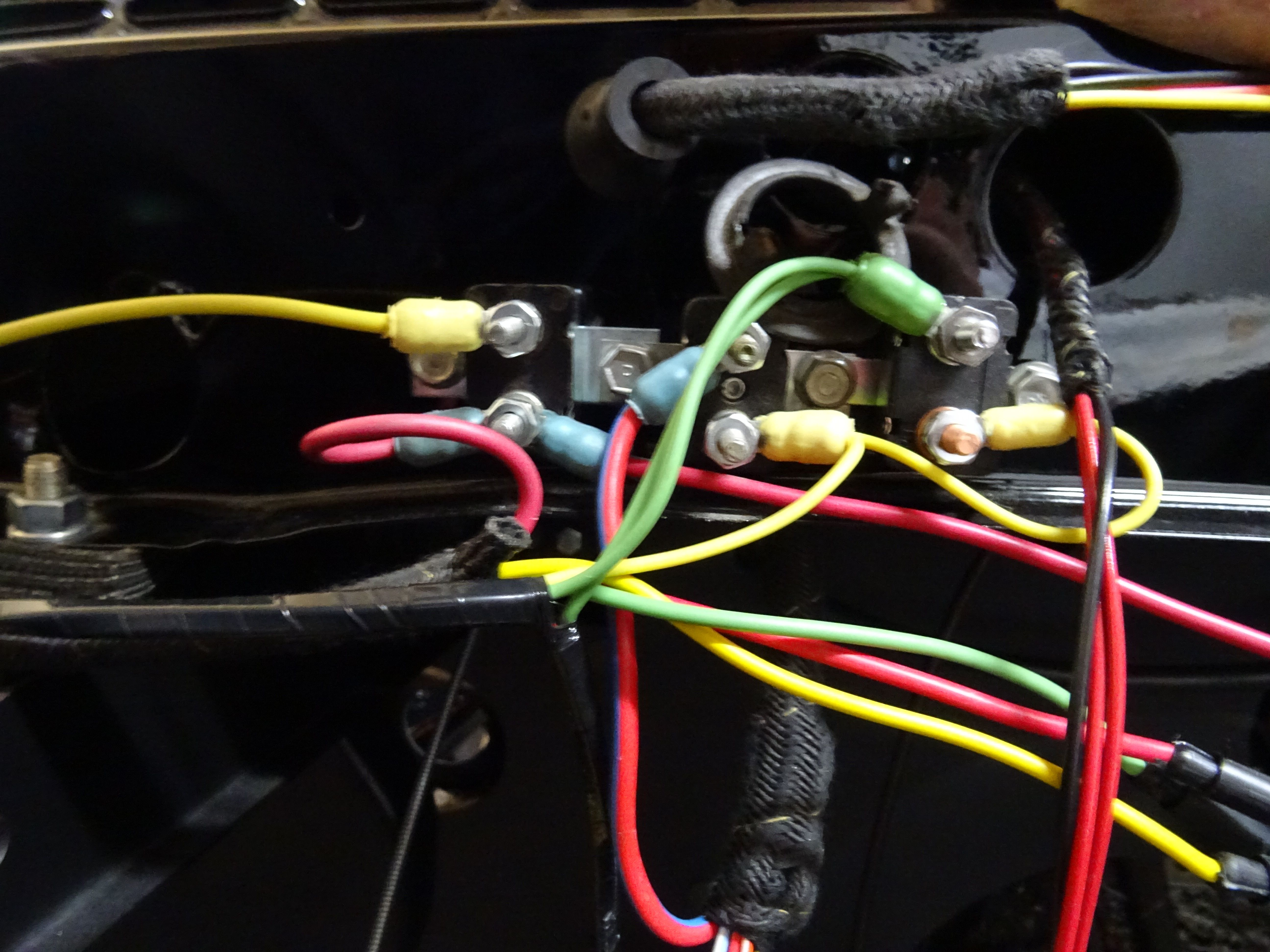
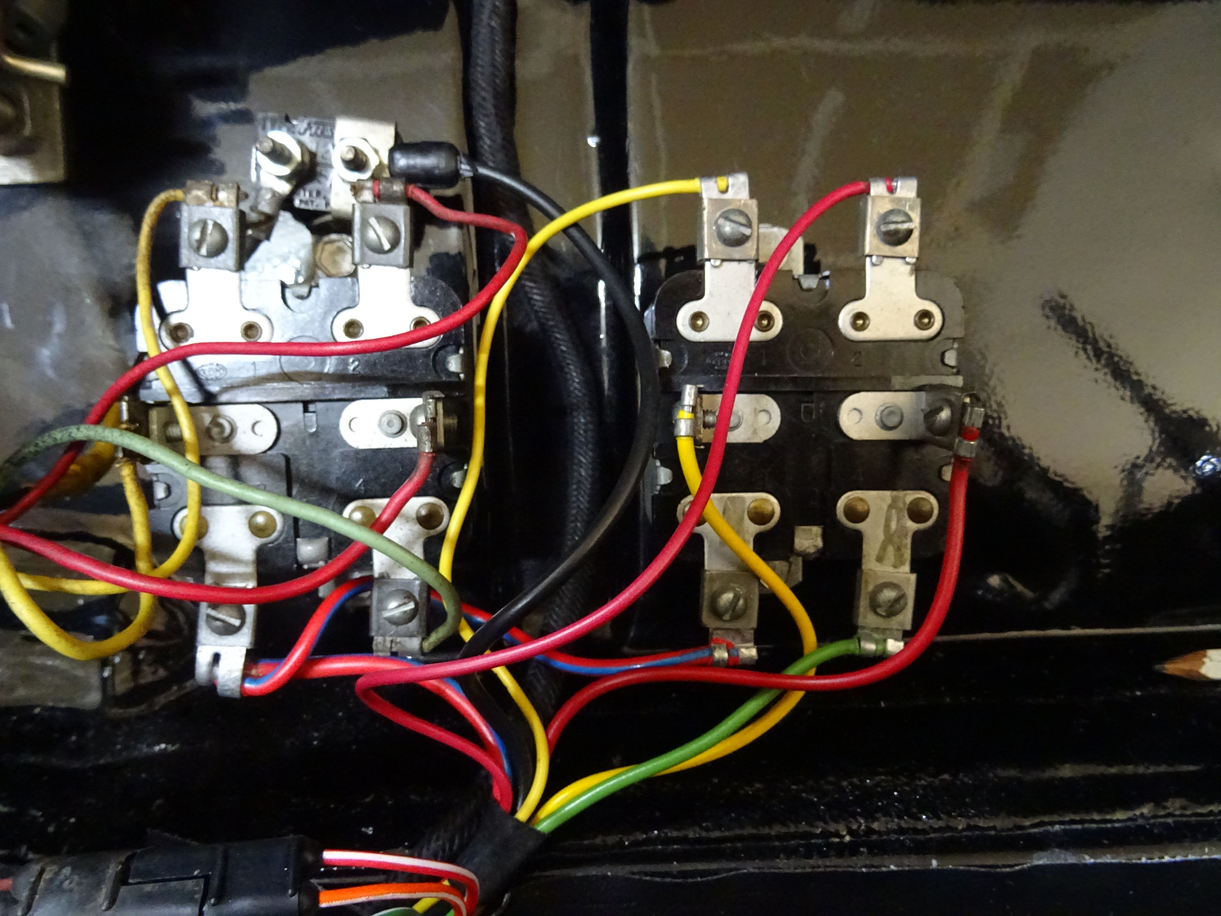
Photo # DM3. shows three overload circuit breakers. The circuit breaker on the left is for the power windows. The yellow wires connected to the battery side of the starter relay provides voltage to all three breakers. The red wires with blue ends provide voltage to the window switches.
The red wire with blue strip on the top center circuit breaker supplies voltage to both seat relays behind the seat. The right hand circuit breaker with the double green wire on the top stud provides voltage to the entry relay, mounted on the firewall and the up/down (vertical) switch mounted on the lower dash.
Photo # DM4. shows the seat relays mounted behind the seat. The relay on the left is for the up/ down (vertical) motor. The forward/aft (horizontal) motor relay is on the right. Power is supplied to both relays at all times through the red with blue strip wire in the lower left corner of each relay.

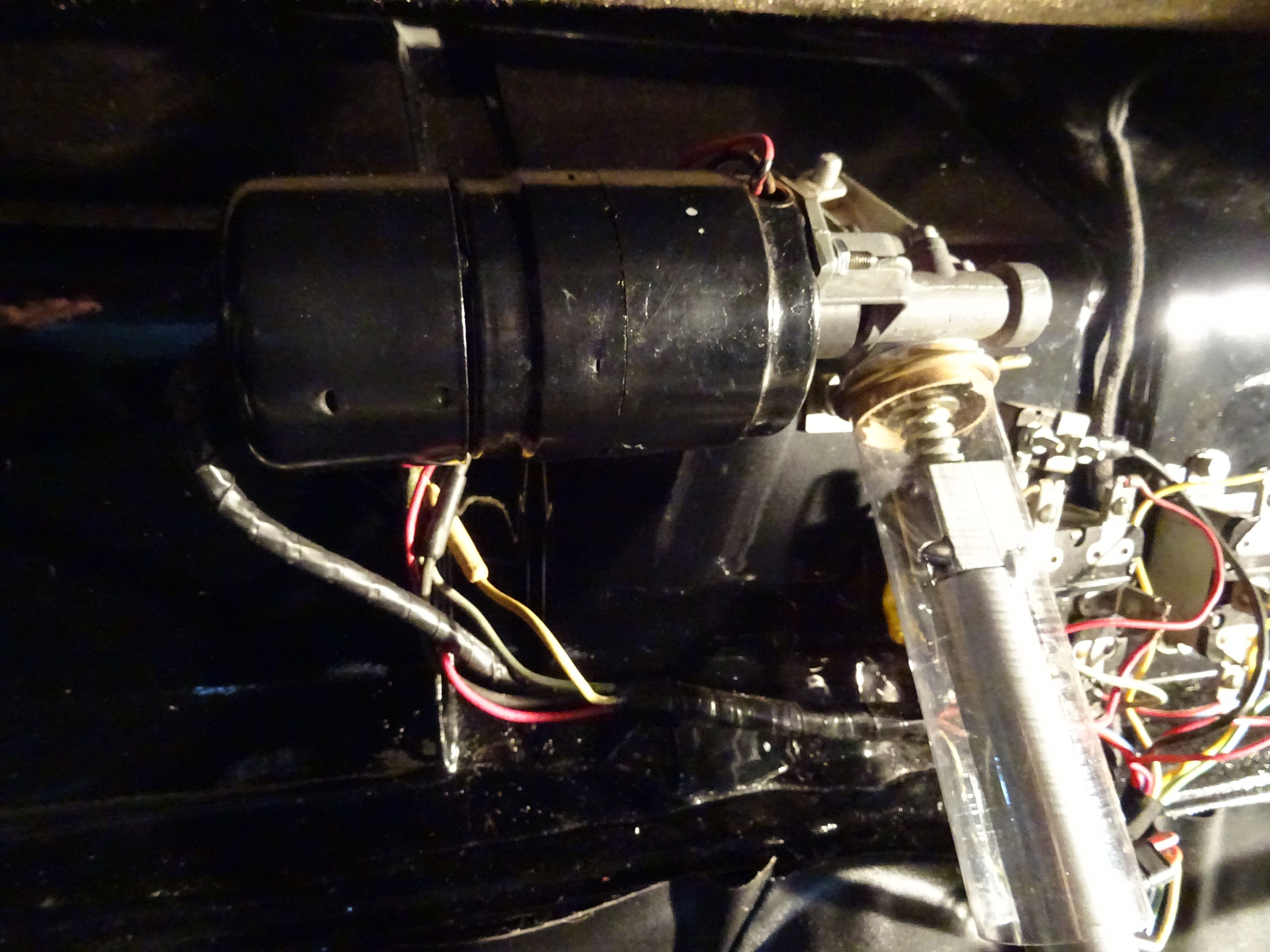
Photo # DM5 shows the forward/aft (horizontal) motor mounted to its floor bracket. It is highly recommended that both motors be checked for operation in both directions before being connected to the seat.
Photo # DM6 shows the rear seat motor with wafer switches mounted in its proper position behind the seat.
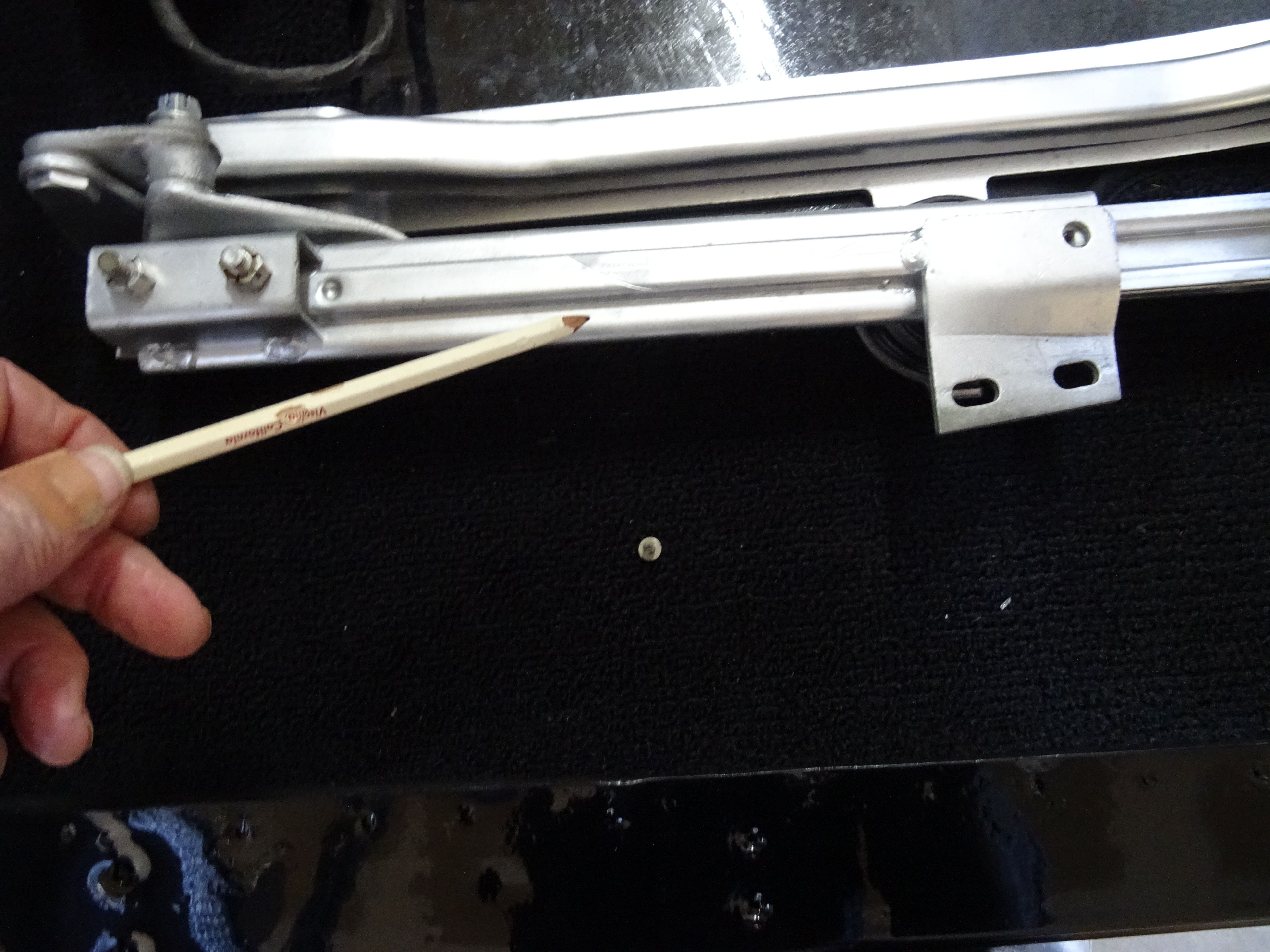
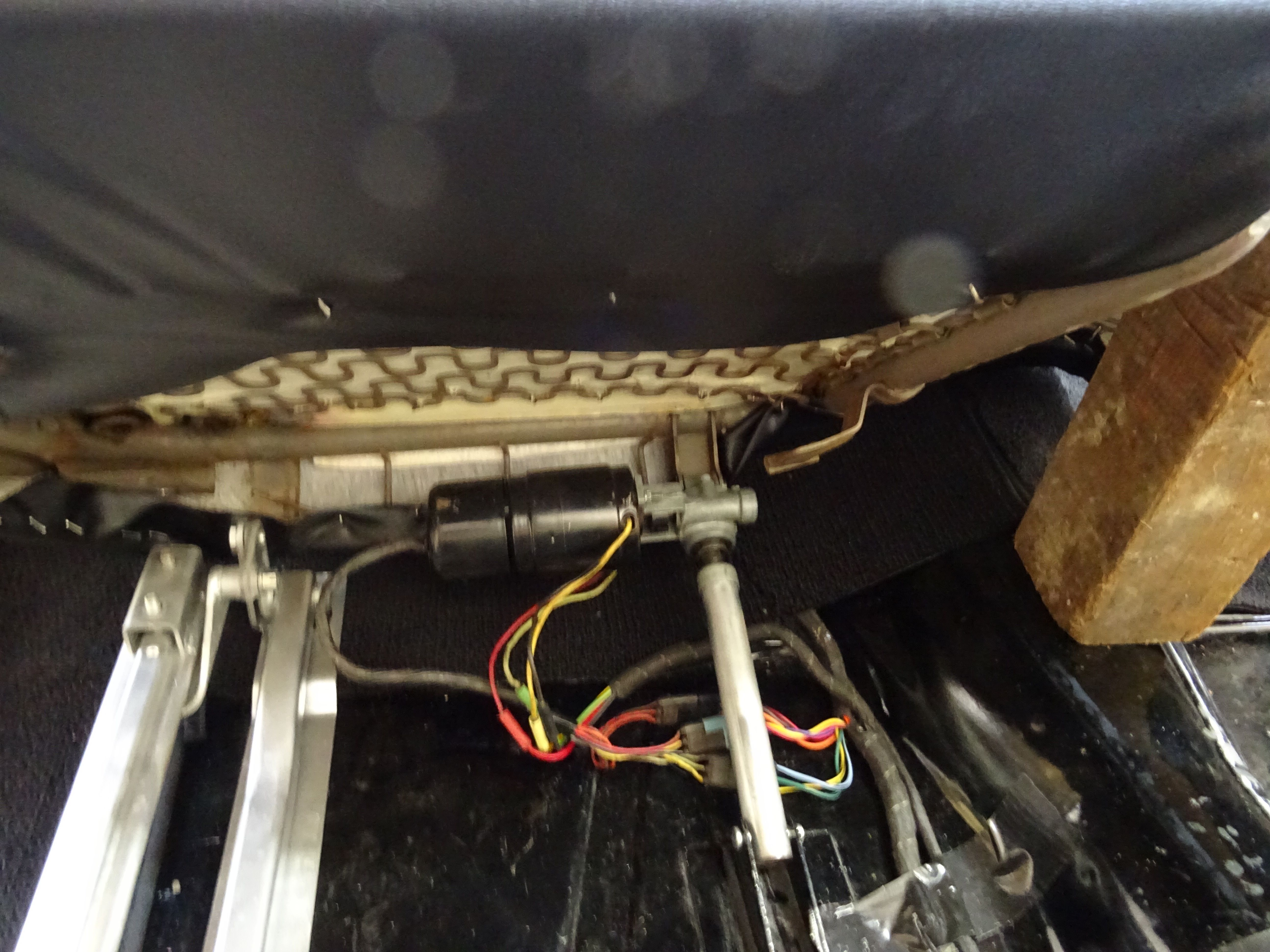
Photo # DM7 shows the seat track assembly mounted to the floor before bolting the seat to the tracks. The next step is to time the motors to the seat track. 1- Place the seat track assembly in the full up position by pushing the cross bar down as far as it will go. 2- Place the center knob on the control switch to position A which is the fully extended position of the rear seat screw actuator. 3- Extend the screw actuator manually to its extended position. It can now be connected to the cross bar on the seat tracks. If all electrical connections are made the up down positions can be checked for proper operation position A – E.
The next step is to time the forward aft motor/actuator movement to the tracks this can be accomplished by manually moving the sliding tracks to full forward position then connect the forward /aft seat motor/actuator to the floor bracket.
Photo # DM8 Next install the lower seat cushion assemble only with the sliding tracks pushed all the way forward. The forward/aft motor/actuator must be extended, position 7 on the control switch. The lower seat can now be positioned on the tracks by carefully lowering into position. With the seat is in full up position the front seat to frame mount bolts can be installed from under the seat on both sides also install the nuts at the rear of the seat on both sides.If the seat motors/actuators are properly timed to the seat assembly the control switches can be used to check all positions. If the circuit breakers release during the operational check the motor/actuators are not properly timed to the seat or the seat tracks are hanging up. After a satisfactory operationally check the upper seat back can be installed on the lower seat cushion assembly.
The Electrical manual has very helpful information & diagrams on page 85, 118, & 119. The manual is available from CTCI.
Gil Baumgartner